
Can a twin screw blower beat the roots blower?
The technical evolution in the blower market for small volume flows has been very poor in the past 50 years. The step to achieve significant progress in energy efficiency in the low-pressure market, is taken by introducing blowers using internal compression instead of external compression.
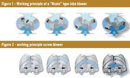
Rotary lobe blowers, also known as “Roots” type blowers, are positive displacement machines consisting of a pair of two lobed or three lobed rotors, rotating inside an oval shaped casing (Figure 1). One rotor is driven by external power while the other rotor is driven by synchronisation gears.
As the rotors rotate, air is drawn into the inlet side and forced out the outlet side against the system pressure. There is no change in the volume of the air within the machine but it only displaces the air from the suction end to the discharge end against the discharge system resistance.
The oil-free screw blower is a positive displacement rotary machine, consisting of male and female rotors, which move towards each other while the volume between them and the housing decreases (Figure 2). The rotors don’t make contact and are synchronised by timing gears. Each screw blower has a fixed, integrated internal pressure ratio. This means that the outlet port is designed and manufactured to a certain fixed geometry. To attain the best efficiency the internal pressure ratio must be adapted to the required working pressure.
Theoretical study
At the lobe blower delivery side, air at a higher pressure is present. When the rotor lobes uncover the exit port, air from the delivery side flows back into the flute space between rotor and casing (Figure 3). This back flow of air equalises pressure and compresses the entrapped air externally at constant volume [1-2]. The air is forced further to the discharge line against the full system pressure [2-3].
With a screw blower at the beginning of the compression cycle, gas at suction pressure fills the flute spaces as the rotors unmesh under the suction flange (Figure 4). Gas continues to fill the flute spaces, until the trailing lobe crosses the inlet port. At that point, the gas is trapped inside the flute space (= stroke volume Vs). On the underside, the rotors begin to mesh. As the lobe meshes into the flute space, the flute volume is reduced, causing the pressure to increase. The volume reduction and subsequent pressure increase will continue as long as the gas is trapped in the flute space. Gas is discharged from the flute space when the leading lobe crosses the discharge port (discharge volume = Vs / vi). Further rotation and meshing of the rotors forces this gas to the discharge line.
Due to the internal compression, the energy consumption is reduced as represented in a pV-diagram by the lighter colour area in Figure 5.
For the best efficiency, the volume ratio vi should be sized so that the internal compression ratio matches the system compression ratio: pi = pe. If the internal compression ratio does not match the system compression ratio, the result is either over compression or under compression.
In over compression (Figure 6), the gas is compressed more than the system requires. Gas is compressed internally to a higher pressure and then expands down to external working pressure. Extra work is required to compress the gas to the internal discharge pressure, rather than to the system discharge pressure.
With under compression the internal discharge pressure is lower than the system discharge pressure and gas from the discharge line flows back into the flute space and equalises pressure at constant volume, resulting in extra work required.
Adiabatic efficiency
The ideal compression process from p1 to pe is a reversible adiabatic (i.e. isentropic) process. The theoretical maximum efficiency in case of “Roots” blowers is 76.5% at a pressure ratio of 2, while a tuned screw blower could reach 100%. Due to dynamic losses at inlet and discharge side, leakages and friction, the real compression work is increased, and subsequently the adiabatic efficiency will be reduced. These effects can be taken into account by definition of an energetic efficiency.
The extra compression work for a lobe blower, compared to a screw blower, results in extra heat dissipation (= power loss) and consequently a higher outlet temperature.
Most compressed air applications that use blowers in both industrial and wastewater markets, require a blower that is able to change the delivered air flow. This can be accomplished by cycling the blowers, throttling the suction, adjusting outlet diffuser vanes, or using adjustable speed drives. In most small flow blowers it is the latter that is the preferred choice.
The change in efficiency is a very important issue to understand as most applications do not always need the exact amount of air that is produced when a blower is running at its maximum flow. In this a screw blower maintains a more stable efficiency compared to a lobe blower.
Pressure pulsations
Traditionally, “Roots” blowers were designed around two lobed rotors.
Lobe blower manufacturers put a lot of effort in trying to reduce the pressure pulsations from this two-lobe design. As the pressure in the pocket is below discharge pressure when the pocket opens to the discharge line, a sudden backflow will occur, accentuating gas pulsations.
Tri-lobe rotors offer a smoother flow and for further reduction of pressure pulsations, helical rotors and special canals are milled in the blower casing to pre-fill the reverse chamber. The strong pulsating torque can lead to intermittent noise and vibration problems (rattle) in the gearing mechanism. Screw blowers deliver a more stable flow and thanks to a better matching of the internal pressure to the external pressure, pressure pulsation levels are reduced. The higher rotational speed and the higher number of lobes results in a higher pulsation frequency. Pulsations with higher frequencies are easier to dampen and result in lower noise levels and lower pulsation levels in the system discharge line. This design prolongs the lifetime of the flexible elements of aerating systems and protects conveyor systems against undesirable pulsations.
Inside the blower, the reduction in pulsations results in fewer vibrations transmitted to the bearings, increasing the bearing lifetime.
Experimental comparison
From a customer point of view, it’s often difficult to compare the energy efficiency of machines using different technologies if the available data is not presented in a comparable manner. “Roots” blower data is commonly offered by giving the air intake flow volume and the shaft power of the bare element. Low pressure compressors are quoted by listing the FAD (free air delivered) at the unit outlet and the power consumption at the terminals of the power supply. This means that air-flow path losses as well as electrical and mechanical transmission losses are not considered in the data of lobe blowers while they are taken into account in the low-pressure compressor data. In order to make the available “Roots” blower data comparable to other technologies, the efficiencies and losses of the other blower components have to be determined.
The air flow path before and after the blower element includes air-inlet filter, air-inlet silencer, air-outlet silencer and the check valve. The pressure drop over these components has to be added to the performance data of the “Roots” blower element.
The transmission losses from the terminals of the power supply to the shaft power of the blower element, consists of the losses of the electric motor and the transmission losses (belt drive) from motor shaft to the element.
These losses vary generally as a function of the blower size and the operating point. Table 1 lists typical values for a small “Roots” type blower (1,000 m³/h) operated at 0.7 bar(e) and medium sized blower (5,000 m³/h) operated at 0.5 bar(e).
Of course, screw blowers also have air flow path and transmission losses, but they are already taken into account when listing the system data, measuring at the power supplies and the compressed air outlet.
Laboratory test
The only way to properly compare the performance of machines is a laboratory test in which different technologies work in the same environment under equal operating conditions, while using the same measurement equipment.
The test series has been performed on different power ratings and various brands of “Roots” blower manufactures. The test results are expressed in the specific energy requirement (SER in J/l), which shows the relation of the consumed power (in kW) divided by the free air delivery (FAD in m³/h). In the first test set-up, a tri-lobe “Roots” blower sized with a 110 kW motor and connected to a separately installed frequency converter is compared to a screw blower using a 75 kW motor with integrated frequency drive. The results are shown in Table 2.
In addition to these tests it was decided to allow TÜV Rheinland to witness the testing of a screw blower against a tri-lobe blower, which resulted in the same findings.
Conclusion
In this paper we have considered an energetic study between a traditional “Roots” blower and a screw blower. The experimental results show a strong correlation with the basic thermodynamic laws and present a screw blower as a more efficient machine, even up to 50% less energy consumption.
Authors:
Gert Van Leuven, Stefan Henneberger and Conrad Latham, Atlas Copco Airpower NV, Wilrijk, Belgium
Join 26,000+ subscribers
Subscribe to our newsletter to stay updated about all the need-to-know content in the feed sector, three times a week.


 Beheer
 WP Admin
  Bewerk bericht