GTC™ Technology guides materials to collide
There are two key reasons for high-energy, low throughput and a rise in temperature of ground materials coming from a hammer mill: poor hammer mill capacity and poor screening capacity. With GTC Technology these problems can be overcome.
Poor hammer milling capacity causes large amounts of colliding energy to waste as heat due to the high rate of eccentric collision. This only makes materials spin and bounce around in the grinding chamber, and does not lead to further size reduction. On other occasions there’s definitely a material circulation layer being swept along the inner surface of the screen, hindering correctly sized particles from getting through the screen holes in time. As these particles rub against the screen, each other and are crushed by hammers, their size is continually reduced by attrition and collision. Energy is wasted in the production of heat, while throughput is restricted and particles sizes become too small.
GTC Technology is a size reduction method that manages to guide the fluidised-bed of material to collide with the hammers:
- It greatly increases the probability of frontal collision between materials and hammers requiring same energy consumption;
- It makes full use of the kinetic energy within the fluidised-bed of material, and succeeds in enlarging impact capacities 31 times that of a single rotor hammer mill;
- It stops the formation of a material circulation layer effectively;
- It highly improves the efficiency of screening capacity by enlarging the effective screening area by 20% and keeps agitating the fluidised-bed of material, thereby reducing the density of the material layer against the screen surface;
- It promises to produce over 40% more throughput under the same energy consumption. In other words, it saves more than 30% on the energy requirement under same production capacity;
- It promises temperature rises of less than 15ºC when grinding aquatic and poultry feed.
Poor hammer milling capacity
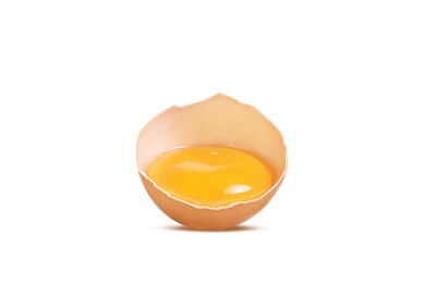
Materials, such as corn could be broken up by using little energy in frontal collision. However, much power is needed for eccentric collision. This is because for eccentric collision, there is a moment of gyration generated between the impact point and the barycenter (centre of mass) of the corn. In general, it only makes the corn spin but does not necessarily break it up.
That falls into the category of elastic collision; the impact power turns into the form of heat which is wasted.However, corn could be broken up along its mid-point and maximum length due to the bending moment if the impacting speed is fast enough. During the process of milling with hammer mills, eccentric collision happens mostly, with large amounts of energy being wasted.
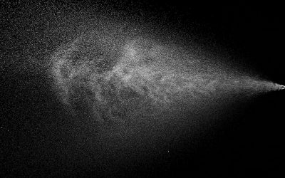
Therefore, methods used manage to increase the probability of frontal collision between the materials and hammers and also enlarge the impact velocity that improves the efficiency of hammer mills.To see what’s going on in a working hammer mill, researchers designed an experiment using high speed photography technology. High-speed photography required a specially designed hammer mill in order to study these effects. One side of the hammer mill was equipped with Plexiglas; the whole grinding chamber was visible through a 10mm outside screen. Two videos were captured separately when grinding corn at normal load and below normal load. Videos were analysed and processed in a professional image processing system.Some typical corn particles were tracked and their movements were captured (Figure 2-3). It could be seen from the video that there is definitely a material circulation layer formed on the screen surface in the chamber.
The corn particles first tracked did not fall into the hammer impacting area. They moved on to the hammer impacting area along the hammer rotating direction, and rebounded into the hammer impacting area after colliding with the screen. Reason for this phenomenon includes the fact that corn fed into a hammer mill with low speed cannot pass through the material circulation layer.
The first tracked corn particle was broke up within 0.4ms at a relative speed 57.45m/s when frontal colliding with the hammer. The second tracked corn particle rebounded into the hammer impacting area after it collided with the screen, as the first one had done.
However, it spun and bounced in the chamber when there is eccentric collision, colliding with a hammer. It needed further impacting in order to achieve size reduction. Eccentric collision happened mostly in the two videos.
Poor screening capacity
According to the traditional size reduction theory in working hammer mill chambers, and due to centrifugal force, bigger particles stay tight and close to the inner screen surface while the smaller particles are further away from the screen. Big heavy particles are difficult to exit through the screen holes and block the holes, while small light particles are far from the screen hole. They also cannot easily exit through the screens, thus forming a material circulation layer with outer big particles and inner small ones.In view of the above, various shapes of grinding chambers were developed to disrupt the material circulation layer, such as hexagonal, elliptical, water-drop, etc. However, some researchers carried out corn grinding experiments to compare chamber shapes. They found that when feeding was at low speed, chambers’ capacities per kilowatt were higher in round, hexagonal, elliptical and water-drop shaped chambers. But when feeding at a higher speed, capacity per kilowatt in the hexagonal and elliptical chambers were lower than in the round one, while the water-drop was similar to round one. This is because when feeding at a higher speed, stagnated materials appear at every corner of the hexagon, at the two ends of ellipse and top frontal impacting screen area of the water-drop chamber.Stagnated materials reduce real screening area and as big particles find it hard to bounce at these places, capacity drops. If you continue to increase the speed of feeding, the stagnated materials will grow in size to fill the chamber so that it becomes a round one and the real screening area is sharply reduced.
In reality, however, big and small particles are distributed evenly in the material circulation layer; density distribution is near the inner screen surface as density is increased, so that the material circulation layer is looser on the inner area and tighter on the outer area. Therefore, reducing the density of material on the inner screen surface can largely improve the screening capacity of hammer mills.Researchers designed a special hammer mill (see Figure 4) to obtain material circulation layer distribution data directly, which revealed the truth.
There’s a fixed partition between grinding chamber and fan chamber. Eight sampling probes (four as a group) were installed in a radial direction evenly spaced on a fixed partition.Sampling probes connect the grinding chamber and fan chamber (negative pressure), high porous sampling bags covered the end of the sampling probes to the fan chamber side. By these means distribution data of material circulation layer along radial direction could be obtained. Main technical parameters of the hammer mill are:
- Width of screen: 200mm
- Diameter of screen hole: 2mm
- Motor power: 5.5kW
- Hammer tip speed: 60m/s
- Feeding speed: 700kg/h
- Corn moisture content: 12.5%
- Single grinding quantity: 9.5kg
Researchers checked the materials collected from each sampling probe and found that average particle sizes was similar along the entire radial direction. Total average particle size of all samples was 1.12±0.04mm. (Total sample size was calculated by mixing all samples of all probes)
Density (material mass per volume unit) distribution of the material circulation layer along the radial direction changed from low to high. That is, at the bottom of the layer, which was close to the inner screen surface, density was high. Closer to the centre of the chamber the density became lower.
GTC Technology
The so-called GTC Guide (a fluidised-bed material diversion plate) ensures high probability of frontal collision between fluidised-bed of material and hammers. The GTC Guide is a plate similar to a cuboid, whose shape is a parallelogram with two sides bowing inward. It is installed between two rotors and through the centre of the grinding chamber, which separates the whole chamber into chamber A and B.
It blocks the whole chamber’s centre space; chamber A and B could communicate through the tunnel at the top and bottom of GTC guide. So the GTC guide can guide as well as divert:
- Guide: GTC guide guides material into neighbouring chamber’s hammer impacting area at a suitable angle, making moving direction of the fluidised-bed of material in the opposite direction to that of the hammer.
- Divert: GTC guide avoids low-efficiency collision between 2 fluidised-beds of material in two chambers, and ensures high probability of frontal collision between fluidised-bed of material and hammers.
Enlarged impacting capacity
Fluidised-bed of material collides with the hammers of the neighbouring chamber in opposite direction; at a speed around 70% of hammer tip speed and thus enlarging GTC hammer mills’ impacting capacity 31 times compared to single rotor hammer mills.
Hammer milling capacity and efficiency is highly improved; temperature rise of ground material is obviously lowered. As mentioned before, the density distribution of fluidised-bed of material is that the nearer the inner screen surface the greater the density, so fluidised-bed of material is loose near the inside and tighter on the outside. Consequently, reducing the density of material on the inner screen surface can largely improve the screening capacity of hammer mills.
Join 26,000+ subscribers
Subscribe to our newsletter to stay updated about all the need-to-know content in the feed sector, three times a week.